A brief description of the various processing units within an integrated gasification combined cycle system is given below in reference to the block flow diagram (Figure 2) discussed under Typical IGCC Configuration. A more detailed discussion of each of the processing unit sections is available; links are embedded in the following discussion.
Preparation Section
As-received (AR) coal from storage is sent to the feed preparation section where it is ground with water through rod mills to form slurry with 62-to-68 wt% dry solids for feed to the slurry-fed GE and E-Gas™-based IGCC plants. Slurry from the grinding mills is stored in agitated storage tanks before being pumped into the gasifiers.
For the dry feed Shell-based IGCC plants, AR coal from storage is ground and dried with hot flue gases through grinding mills to produce a 2-to-5 wt% moisture coal fines for feed to the Shell gasifiers. The dried coal fines are stored in surge hoppers before being pressured with nitrogen to the gasifiers through lock-hoppers and dense phase pneumatic conveying systems.
Gasification Section
For GE gasification-based IGCC, slurry feed is pumped to the refractory-lined gasifier where the coal is gasified with oxygen (O2) from the air separation unit (ASU) to generate a raw syngas (SG) consisting primarily of hydrogen (H2) and carbon monoxide (CO). Heat in the gasifier liquefies the coal ashes. The molten ash is then quenched and crushed at the bottom of the gasifiers before being dewatered for disposal. The raw SG is sent to the downstream High Temperature Gas Cooling (HTGC) section for heat recovery.
The E-Gas™ gasification process is similar to the GE gasification except for the two-stage slurry feed system. Roughly 75% of the slurry feed and all of the O2 are sent to the bottom (first) stage of the gasifier where the highly exothermic gasification/oxidation reaction takes place at high temperature. Hot syngas from first stage is mixed with the remaining 25% of the slurry feed in the top (second) stage where the highly endothermic gasification/devolatilization reaction takes place to produce a cooler SG exit to the HTGC.
The Shell gasification process is similar to the GE gasification except that the coal feed is pressured into the gasifier dry. Small amounts of steam are also added to meet minimum system water and H2 requirements.
High Temperature Gas Cooling (HTGC)
Raw SG from the gasifier is cooled to about 650-700°C (1,200-1,300°F) in the HTGC section by generating high pressure (HP) saturated steam in a radiant syngas cooler for GE-based IGCC. For E-Gas™-based IGCC, raw SG from the gasifier is cooled to about 370°C (700°F) by generating HP superheated steam in a fire-tube convective syngas cooler. For Shell-based IGCC, raw SG from the gasifier is first quenched to below the ash melting temperature with recycle cooled syngas, before being cooled to about 316°C (600°F) in the HTGC section by generating HP superheated steam in a fire-tube convective syngas cooler. Cooled syngas from the HTGC is sent to the particulate removal section.
Particulate Removal
For GE-based IGCC, syngas from HTGC is quenched and scrubbed with water to remove particulates, hydrogen chloride (HCl), and ammonia (NH3). For E-Gas™ and Shell-based IGCC, syngas from HTGC first passes through cyclones and candle filters to remove a bulk of the particulates before being scrubbed with water to remove the remaining fines and HCl and NH3.
COS Hydrolysis
Because carbonyl sulfide (COS) is not easily removable by most acid gas removal (AGR) processes, it is necessary to convert COS into hydrogen sulfide (H2S) before AGR in order to meet sulfur dioxide (SO2) emission limits. Scrubbed syngas from the Particulate Removal section is reheated to about 205°C (400°F) before entering a catalytic COS hydrolysis reactor where over 90% of the COS reacts with water to form H2S and carbon dioxide (CO2).
Low Temperature Gas Cooling (LTGC) and Mercury Removal
Syngas exiting the COS Hydrolysis section is cooled to about 38°C (100°F) through a series of heat exchangers and knockout drums in the LTGC section before going to the mercury removal section, where over 90% of the mercury is removed through adsorption on to carbon beds.
Acid Gas Removal (AGR)
Cooled particulate-free syngas enters the AGR absorber where nearly all of the H2S and small amount of the CO2 are removed through absorption by lean solvent. H2S free syngas exiting the absorber top is sent to the downstream humidification and reheat section. Rich solvent exiting the absorber is flashed through depressurization, or stripped with nitrogen (N2) to remove excess CO2 and other non-sulfur bearing gases such as H2 and CO before going to the regenerator. The flashing or N2 stripping step is necessary to reduce the non H2S components in the rich solvent so the acid gas from the downstream regenerator contains at least 25% H2S in order to maintain furnace combustion temperature in the downstream sulfur recovery unit. The flashed gas or N2 stripped gas is scrubbed with lean solvent to remove H2S before being compressed and sent to the gas turbine combustor as part of the fuel supply. The flashed rich solvent is sent to the regenerator where the H2S and CO2 are stripped off with reboiler steam. Lean solvent from the regenerator bottom is cooled and recycled back to the absorber. Acid gas from the regenerator overhead is sent to the next unit for sulfur recovery.
Exact AGR solvent selection depends on process conditions. For HP GE-based IGCC with the AGR operating above 5 MPa (715 psia), a physical solvent such as Selexol or a chemical solvent such as MDEA can be used. Below 3.5 MPa (500 psia), MDEA or some other chemical or mixed solvent would be considered.
Sulfur Recovery Unit (SRU) & Tail Gas Treating Unit (TGTU)
Acid gas from the AGR stripper is sent to the SRU where one-third of the H2S is burned with oxygen from the ASU to form SO2. The SO2 is combined with the remaining two-thirds of the H2S before being catalytically converted into sulfur via the Claus reaction:
SO2 + 2 H2S → 3 S + 2 H2O
Tail gas from the SRU is normally hydrogenated to convert unreacted SO2 and entrained sulfur into H2S before being compressed for recycle to the AGR or the gasifiers to eliminate the need for a separate TGTU. For the Shell-based IGCC, a TGTU is included since the TGTU vent incinerator flue gas can be used to dry the coal feed.
Clean Gas Humidification and Reheat
Clean syngas from AGR is humidified by washing against hot circulating water to add steam for nitrogen oxide (NOx) control and to recover some of the low-level waste heat. The humidified syngas is reheated through heat exchange against raw syngas before being sent to be burned in the gas turbine (GT). For the HP GE-IGCC, the hot, clean syngas is depressurized through a fuel gas expander to recover some power before being burned in the GT.
Turbines in the IGCC Plant
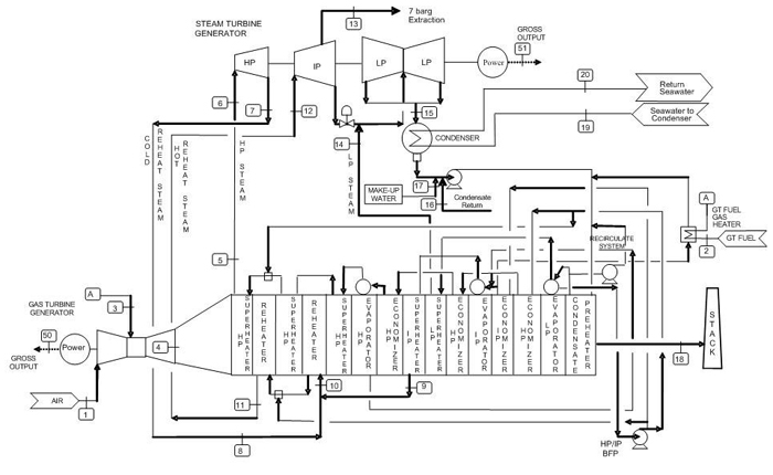
In IGCC applications, the clean synthesis gas (syngas) is burned in high efficiency, low emission gas turbines (GTs) to generate electricity. The GTs utilized are derivatives of proven natural gas combined-cycle machines that have been specially adapted to burn syngas. Hot exhaust from the GT is cooled through a heat recovery steam generator (HRSG) to generate high pressure superheated steam to make additional power in the steam turbine. The combined cycle plant is supported by a host of utility processing facilities such as steam/condensate collection and distribution, cooling water, boiler feed water and wastewater treatment systems. The GT and HRSG are shown in additional detail in the following figure.
Simplified Flow Diagram of a Typical Combined Cycle Plant
Gas Turbine
Clean syngas is burned with compressed air and diluents in the gas turbine to generate power. Modern GTs have been modified from conventional NG turbines, and commercially demonstrated to be able to burn low and medium BTU syngas from coal gasification. The GT rating for syngas firing can be approximately 5-15% higher than that for natural gas firing due to the higher mass flow. For IGCC with carbon capture, the GT must be adapted to burn syngas with essentially no CO (see discussion of hydrogen turbines). Current state-of-the-art GTs are commercially ready to burn syngas with up to approximately 60% hydrogen with the balance being nitrogen or/and water as the diluent. Work is on-going to develop the next generation of high efficiency GT for carbon capture-based IGCC. In some oxygen-blown IGCC designs, the GT also provided a portion of the compressed air to the air separation unit (ASU). This increases the overall IGCC plant efficiency and reduces the capital cost and power consumption of the ASU.
Heat Recovery Steam Generator (HRSG) and Steam Turbine Generator (STG)
Hot exhaust from the GT is routed through the heat recovery steam generator to generate 1,800 psig, 1,050°F super-heated HP steam, as well as reheat intermediate pressure (IP) steam to 1050°F without supplemental firing. The HRSG also generates saturated HP steam (and possibly superheats steam as well) from gasification syngas cooling. The HP and IP superheated steam are routed to the steam turbine generator (STG) to generate additional electric power. The STG is an advanced commercially available machine using a 1,800 psig/1,050°F/1,050°F steam cycle.