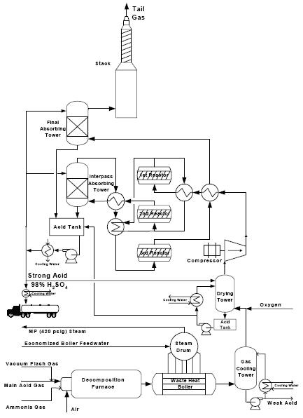
The option to recover sulfur in the form of sulfuric acid (H2SO4) is practiced at Tampa Electric's IGCC demonstration plant, given the local demand for sulfuric acid for fertilizer manufacture in this area of Florida. Figure 1 shows a simplified flow of the Tampa Electric IGCC sulfuric acid plant. The sulfuric acid plant receives the hydrogen sulfide (H2S) from the acid gas recovery unit and H2S and ammonia from the water stripper. The gas streams are then burned in a decomposition furnace, where the H2S produces primarily sulfur dioxide (SO2) with trace amounts of sulfur trioxide (SO3), sulfuric acid and elemental sulfur and the ammonia is converted to nitrogen (N2) and water. The decomposition furnace exit gas is cooled from about 1,950°F to 650°F in a waste heat boiler to produce medium pressure steam for in plant use. The gas is then further cooled and dried. This step produces a 'weak acid' waste stream which needs to be neutralized before discharging into the cooling pond. The SO2 and oxygen (from either air or an air separation plant) then react over a vanadium based catalyst bed in a converter according to the reaction;
SO2 + ½ O2 → SO3
The produced SO3 is then reacted with water as follows:
SO3 + H2O → H2SO4
The catalytic oxidation of SO2 to SO3 is highly exothermic, and the equilibrium becomes increasingly unfavorable for SO3 formation as temperature increases to about 800°F. For this reason, special catalytic converters (reactors) are designed as multistage reactor bed units with air cooling between each bed for temperature control.
Gas from the final reactor beds enters the absorbing towers, where the produced SO3 reacts with the excess water in a circulating, strong (98%) sulfuric acid stream, creating additional H2SO4. This incrementally raises the concentration of the sulfuric acid so that water is introduced as needed to maintain the H2SO4 at 98.5% as the final product.
The Tampa Electric sulfuric acid plant is very efficient, converting over 99.5% of the incoming H2S to H2SO4.
Figure 1: Tampa Electric IGCC Sulfuric Acid Plan Flow Diagram