The basic Claus process for sub-stoichiometric combustion of hydrogen sulfide (H2S) to elemental sulfur follows the following reactions:
H2S + 1 ½ O2 → SO2 + H2O
2 H2S + SO2 → 2 H2O + 3 S1
3 H2S + 1 ½ O2 → 3 H2O + 3 S
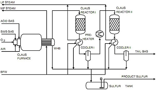
Figure 12 shows a typical process flow scheme of a 2-stage straight-through3 Claus sulfur recovery unit (SRU). Acid gas from the acid gas removal (AGR) process, along with overhead gases from sour water stripping and a small amount of recycle from the tail gas treating unit (not shown), are burned in the Claus furnace with sufficient air or oxygen to produce an overall gas mixture with the desired 2 to 1 stoichiometric ratio of H2S to sulfur dioxide (SO2) for conversion to sulfur and water. A substantial amount of sulfur (about 2/3 of the total sulfur recovered) is thermally formed directly in the furnace by the above reactions. As the hot furnace exhaust is cooled in the waste heat boiler (WHB), the gaseous sulfur is condensed and removed from the gases. Removal of the sulfur from the right sides of the reactions provides driving force for further conversion in the downstream catalytic reactor stages, which occur at increasingly lower temperatures, also favoring more complete conversion to sulfur. The gases are reheated and enter the first catalytic reactor, where about 75% conversion of the remaining gases takes place, followed by cooling, sulfur condensation and removal. Another stage or two follow to recover about 98% of the total sulfur. Reaction heat produced in the burner is recovered in the integrated WHB by generating medium pressure steam, used in both reheating for catalytic stages and outside use.
Sulfur products are cooled and condensed, generating low pressure steam. Condensed sulfur product is stored in an underground molten sulfur pit, where it is later pumped to truck loading for shipment. Claus tail gas from the last stage sulfur condenser is sent to a tail gas treatment unit to remove unconverted H2S, SO2, and carbonyl sulfide (COS) before disposal.
Figure 1: A Typical Claus Process Block Flow Diagram
References/Further Reading
Gasification (2003) by Christopher Higman and Maarten van der Burgt, Elsevier Publishing
1. In practice various allotropic forms of sulfur are involved including primarily S2, S6 and S8. Accurately predicting the formation, behavior and distribution of sulfur in the Claus process stages requires attention to the thermodynamics of all allotropes. 2. Originally from Weiss, M.-M., "Selection of the acid gas removal process for IGCC applications", Paper presented at IChemE Conference "Gasification Technology in Practice", Milan; reproduced in Christopher Higman and Maarten van der Burgt, Gasification, 1st edition, Elsevier Science (2003). 3. A split flow arrangement is also possible in which a significant fraction of the acid gas feed bypasses the furnace and goes directly to the first catalytic stage; selection of flow arrangement depends on multiple factors including concentration of H2S in the feed gas, hydrocarbon content of the acid gas, whether air or oxygen is used to fire the furnace, and preheating of air and acid gas feed streams. A detailed discussion of these complexities is beyond the scope of this discussion; for further information the reader is referred to Chapter 8 "Sulfur Recovery Processes" in Gas Purification, Arthur L. Kohl and Richard Nielsen, Gulf Professional Publishing (1997).