
Carbon Storage Atlas
- Why this Location
- Main Research Q&As Discovered
- Advice for Future Operators
- Field Site Story of Interest
- Geologic Details
- Project Introduction and Site Operations
- Site Characterization
- Risk Assessment
- MVA
- Commercialization
- Sites
Lat/Long
31°5′33″N 88°14′39″W
Why this Location
The Citronelle Project site was uniquely situated to meet the needs of an integrated carbon dioxide (CO2) capture, transportation (via pipeline), and underground storage and monitoring demonstration. The test site is located within the Citronelle Dome geologic structure. The geology at the site meets all the requirements for safe, long-term storage of CO2. The injection zone for the Citronelle Project is the upper Paluxy Formation, which occurs at a depth of 3,000 to 3,400 meters (~9,843 to 11,155 miles) at the Citronelle field, well below the miscible depth for CO2, and is approximately 335 meters (1,100 feet) thick. In this region, the Paluxy is a stacked sequence of porous and permeable fluvial sandstones. It is overlain by multiple geologic confining units that serve as vertical flow barriers and will prevent CO2 from escaping from the storage reservoir. A structure map of the Citronelle Dome shows the structure to have secure four-way closure free of faults or fracture zones (Figure 1).
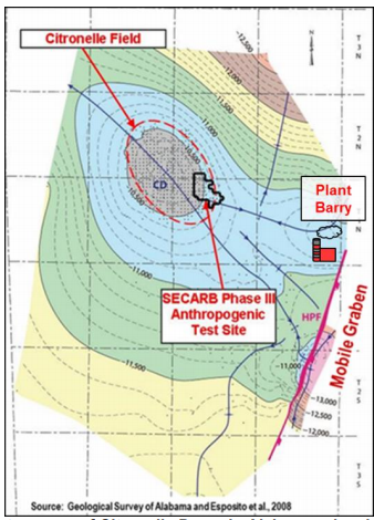
Figure 1: Geologic structure map of Citronelle Dome in Alabama, showing the location of Citronelle field and the Citronelle Project site and regional structural features. Contour interval is approximately 30.5 meters (100 feet).
The Citronelle Dome is located approximately 15 kilometers (~9.3 miles) west of Plant Barry in southwest Alabama (Figure 2), and a pipeline was constructed in 2011 to link the CO2 capture system with the Paluxy Formation. The Citronelle field’s proximity to Plant Barry allowed for the safe and effective transport of CO2 from the capture facility at the plant to the Citronelle field.
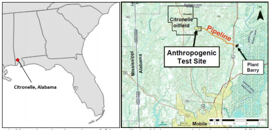
Figure 2: Map showing location of Citronelle in Alabama and the location of Plant Barry.
The existing infrastructure and surface suitability at the Citronelle field were also crucial for the success of the Citronelle Project. The location accommodated well drilling and CO2 injection activities; provided adequate water and electrical supplies to support drilling activities; and met the requirements for the monitoring, verification, and accounting (MVA) program for the project.
Main Research Q&As Discovered
The purpose of the Southeast Regional Carbon Sequestration Partnership’s (SECARB) Phase III Citronelle Project was to test and demonstrate safe, secure carbon dioxide (CO2) injection and storage in regionally significant saline reservoirs.
Project Objectives/Questions and Results:
- What are the most effective strategies for monitoring CO2 storage in Gulf Coast formations such as the Paluxy Formation? And what were the results of adapting commercially available oilfield tools and techniques for post-injection monitoring?
Off-the-shelf industry tools were effectively incorporated into the monitoring, verification, and accounting (MVA) program. For example, there was no evidence of CO2 saturation observed within or above the confining zone based on the results of repeated runs of pulsed neutron capture log. Additionally, cross-well seismic results showed no negative velocity anomalies in or above the confining unit implying no detectable leakage out of the injection zone, as well as effective containment of CO2. - How will the reservoir architecture of the saline formation affect CO2 storage? Can reservoir architecture minimize areal extent of the CO2 plume?
The project modeled the internal reservoir architecture to select multiple injection zones that maximized injectivity and minimized the CO2 footprint and pressure front. - How did testing of experimental CO2 monitoring technologies that are promising candidates for future commercialization impact the project?
Experimental monitoring systems can impact injection and vice versa. Additionally, when deploying non-commercial MVA protocols, redundancy with more commercial tools are necessary to ensure data quality. - How did the permitting, MVA, and compliance process for all aspects of a carbon capture and storage (CCS) project impact the project?
Regulatory approval often involves negotiations and modifications to the operator’s proposed MVA program. The MVA program was tailored to site-specific conditions, project goals, and the regulatory framework in which the project operated.
Advice for Future Operators
Utilizing lessons learned from previous projects will greatly inform the approach to project management and planning for the coordination required to successfully integrate all components of a potential capture, transport, injection, and monitoring project. The Citronelle Project yielded critical lessons learned, which benefit future projects. For example, whenever possible, commercial tools should be used as backup for any experimental monitoring. This redundancy will provide a check to the experimental tools and help to drive the evolution and expansion of the carbon storage monitoring toolkit.
Field Site Story of Interest
Transportation from Plant Barry to the injection site occurs via an approximate 4‐inch diameter pipeline that extends approximately 19 kilometers (~12 miles) from the outlet of the carbon dioxide (CO2) capture facility to the point of injection within Citronelle field. The pipeline route encountered an undulating terrain with upland timber, stream crossings, and a variety of wetland types that were avoided or mitigated if openly crossed to minimize environmental impact. One notable aspect of the pipeline construction effort was the abundance of gopher tortoise (Gopherus Polyphemus) burrows encountered along the right of way. The gopher tortoise is listed by the U.S. Fish and Wildlife Service as a threatened species in the region, and protective actions must be taken when tortoises or their burrows are located. It was determined that directional drilling would be the less-expensive option when compared to the cost to relocate the tortoises. Ultimately, directional drilling was employed to route 18 sections of the pipeline beneath roads, utilities, railroad tracks, wetlands, and, last but not least, the tortoise colonies.
Geologic Details
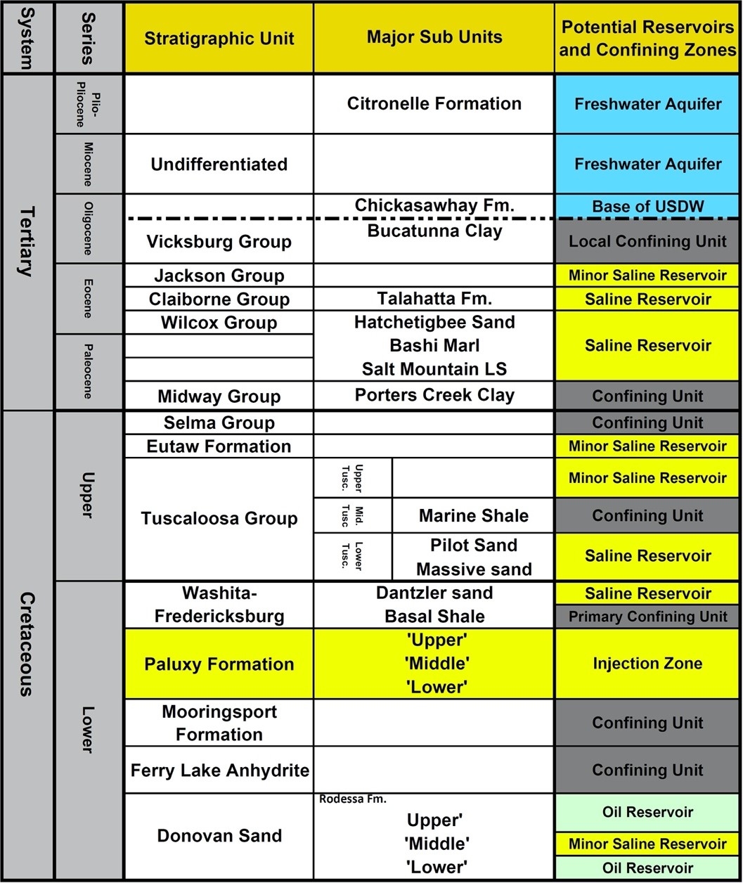
The stratigraphic column (Figure 1) shows the Tertiary- and Cretaceous-age saline reservoirs and confining horizons at Citronelle field. The fluvial sandstones of the upper Paluxy were the target reservoirs for carbon dioxide (CO2) injection. The Paluxy Formation is approximately 335 to 350 meters (~1,100 to 1,148 feet) thick. Confining horizons for the Paluxy include multiple area-scale mudrocks present in the Paluxy and the overlying Washita-Fredericksburg Group. The primary confining horizon is the basal shale of the Washita-Fredericksburg Group. Other confining zones include the Tuscaloosa Marine Shale, the Selma Chalk, and the Midway Shale.
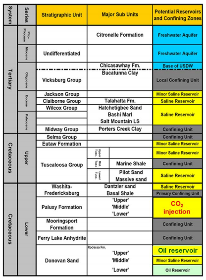
Figure 1: Stratigraphic column showing tertiary and cretaceous formations at Citronelle field.
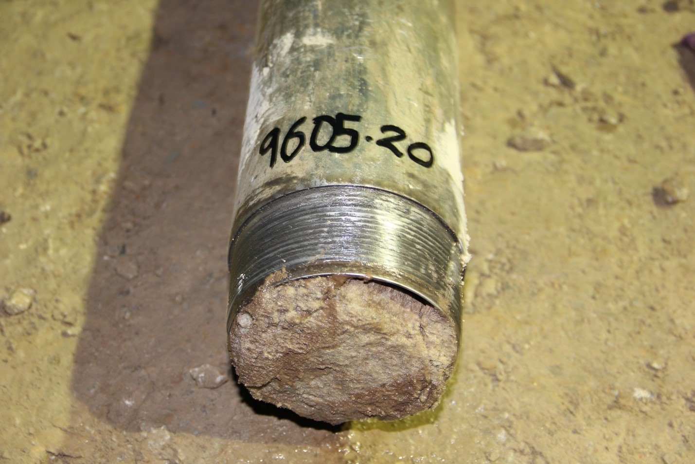
Geologic characterization of the Paluxy Formation is based on core samples that were obtained while drilling the three wells. The middle Paluxy Formation (approximately 137 to 152 meters [~450 to 500 feet] thick) is comprised of mudstone, siltstone, and thin sandstones, representing a near-shore marine environment. The lower Paluxy (approximately 61 meters [200 feet] thick) is comprised of fluvial sandstones that have finer grain size, compared to the upper Paluxy, except for hard, cemented pebble conglomerate at the base of some individual sandstones.
Log data from the wells confirm the presence and lateral extent of the upper Paluxy reservoir sandstones. The stratigraphic cross-section (Figure 2) shows gamma-ray, resistivity, and neutron and density porosity curves for the upper Paluxy CO2 storage horizon in the three wells.
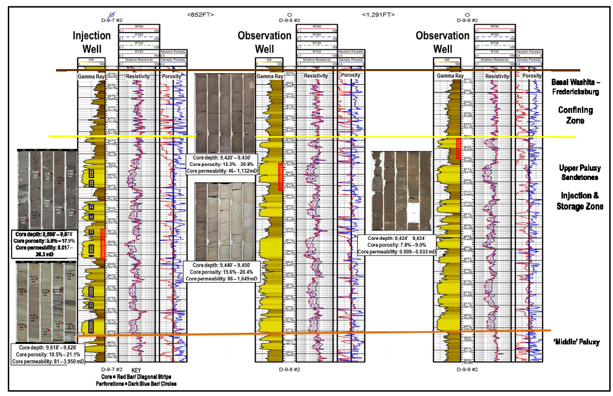
Figure 2: Stratigraphic cross-section of upper Paluxy CO2 injection and storage reservoir at the Citronelle Project Site.
Project Introduction and Site Operations
The Southeast Regional Carbon Sequestration Partnership (SECARB) identified a series of thick, regionally extensive saline formations with high-quality seals that exist within the Gulf Coastal region that have potential to hold large volumes of carbon dioxide (CO2). The Cretaceous-age Paluxy Formation sandstone is the target for the Citronelle Project performed in southwest Alabama. The CO2 source is a newly constructed post-combustion CO2 capture facility at Alabama Power’s Barry Electric Generating Plant. A small amount of flue gas was diverted from Plant Barry and captured using a process developed by Mitsubishi Heavy Industries to produce highly pure CO2. The CO2 storage site is located within the Citronelle Dome geologic structure. The Citronelle Dome, which provides secure four-way closure free of faults or fracture zones, is located approximately 15 kilometers (~9.3 miles) west of Plant Barry. A pipeline was constructed in 2011 to link the CO2 capture system with the Paluxy Formation.
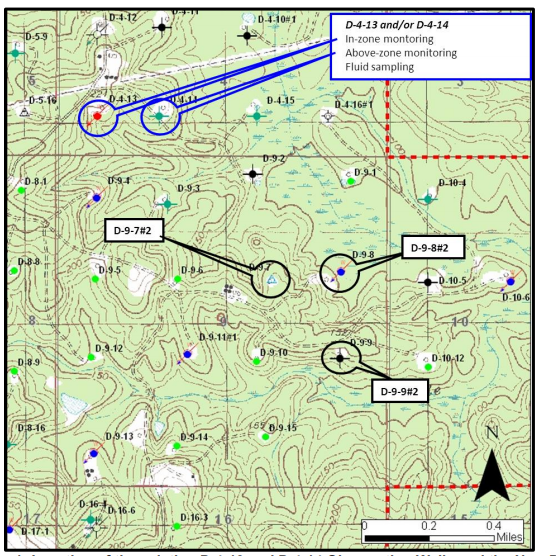
Figure 1: Location of the existing D 4-13 and D 4-14 observation wells and the new D 9-7 #2, D 9-8 #2, and D 9-9#2 wells drilled for the Citronelle Project.
Geologic characterization of the Paluxy Formation is based on core samples that were obtained while drilling the three new wells – a primary injection well, the back-up injector, and the observation well. Additionally, two existing wells were re-completed to serve as up-dip above-zone and in-zone monitoring wells, respectively. Locations of the project’s deep wells are shown in Figure 1. The CO2 injection operations began on August 20, 2012, and were terminated on September 1, 2014. The project entered the post-injection site care phase on September 1, 2014. A total of 114,104 metric tons of CO2 were injected. Figure 2 shows the daily and cumulative CO2 injection volumes.
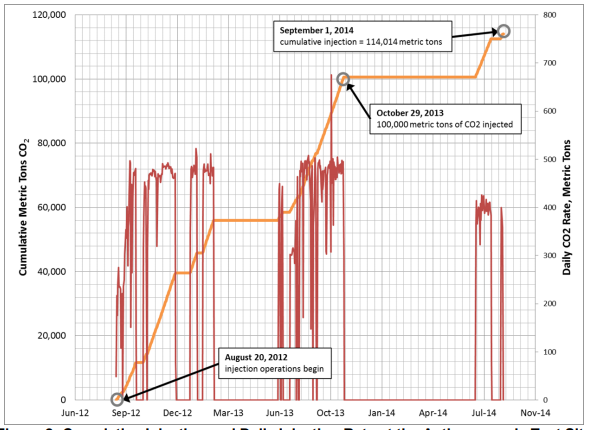
Figure 2: Cumulative injection and daily injection rate at the Citronelle Project Site.
Monitoring of the injection site continued until 2017. All non-endangerment of underground sources of drinking water (USDWs) and CO2 confinement in the injection zone have been demonstrated using modeling and monitoring results, allowing closure of the Class V Underground Injection Control permit in May 2018 and the temporary or permanent abandonment of the project wells.
Site Characterization
The Citronelle Project site is located on the southeast flank of the Citronelle Dome, a part of the Citronelle oilfield. The field forms a structurally simple, fault-free salt-dome exhibiting elliptical, four-way closure that is ideal for carbon dioxide (CO2) storage. It contains multiple reservoir sandstone units and a range of mudstone, evaporate, and carbonate seals. No faults or other geologic discontinuities have been identified in the Citronelle field.
The upper Paluxy Formation, a stacked sequence of porous and permeable fluvial sandstones, is the injection target and is approximately 335 meters (~1,100 feet) thick at Citronelle field. Integration of core facies, porosity and permeability values from core plug analysis, and geophysical well analysis were used to delineate attractive reservoir targets. Reservoir porosity commonly exceeds 20% and permeability values can reach Darcy levels.
Geologic characterization of the Paluxy was based on geophysical well logs and four whole rock cores that were obtained while drilling the injection well and two observation wells. These core analyses provide critical data for reservoir simulation on the target sandstones and primary confining units. Approximately 146 meters (~480 feet) of net porous sand were assessed from the study area’s core analyses in the upper Paluxy Formation. These intervals are distributed in more than 20 sand units, ranging in thickness from approximately 6 to 23 meters (20 to 75 feet). Average core porosity of upper Paluxy sandstones in the three wells is 19.5%. Upper Paluxy sandstone permeability averages 280 millidarcies (mD). However, the coarse to medium-coarse grained intervals at the base of individual sandstones of the upper Paluxy have measured core porosity exceeding 22% and Klinkenberg-corrected permeability to air that can exceed 3,000 mD.
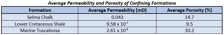
The primary confining unit above the Paluxy Formation is the basal shale of the Washita-Fredericksburg interval, and secondary seals higher in the section provide additional storage security, which includes the Selma Group chalk, an approximately 610-meter (~2,000-foot) regional seal. Permeability values for the primary confining units are shown in the table below, demonstrating low permeability.
Baseline vertical seismic profiles (VSPs) and crosswell seismic were conducted to establish initial subsurface acoustic conditions for later time-lapse monitoring. The results showed good apparent confinement of the upper Paluxy sandstone with no observable reservoir or confining unit discontinuities. Similarly, the processed reservoir images of the baseline VSP shows confinement and no observable structural anomalies.
Risk Assessment
The risk management approach for the operational risks at the Citronelle Project was tailored to the integrated carbon dioxide (CO2) capture, transportation, injection, and monitoring system. The project team worked cooperatively with DNV GL (formerly Det Norske Veritas and DNV Kema) to develop a site-specific registry of communication and project-related risks. Figure 1 shows the DNV risk assessment framework. Risks were identified, assessed for consequence and likelihood, documented early, and revisited often to safeguard human health and the environment. Risk workshops were conducted prior to initiating field activities, prior to the start of CO2 injection, at the beginning of the post-injection monitoring period, and after the well permits were closed and all operations ended.
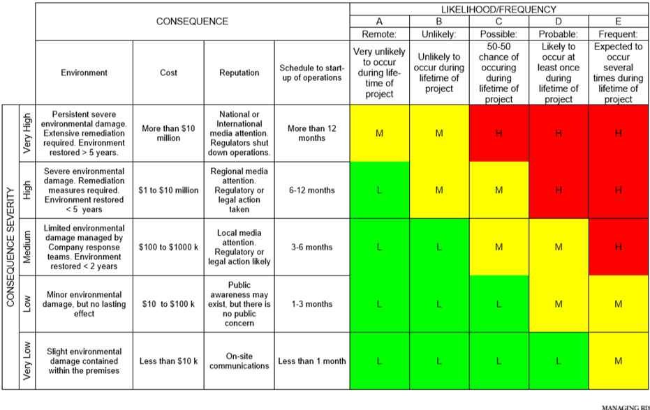
Figure 1: DNV risk assessment framework.
Risks fall within five primary categories: health and safety, environmental protection, cost, reputation, and schedule to start-up integrated operations. The goal is to have risk treatment actions in place to reduce the severity to as low as reasonably possible. No risks were assessed as unacceptable, and the highest risks were related to regulatory uncertainty and successful integration of project components.
In order to accurately model the injection, migration, and long-term fate of the CO2 in the subsurface, GEM-GHG, a Computer Modeling Group software program for reservoir simulation and transport modeling, was selected for the simulation.
Utilizing the extensive data collected during the geologic characterization, as well as a generous amount of information from the field operations, the model was built to replicate the reservoir conditions at the Citronelle Project.
Results of the numerical simulation demonstrated effective containment of CO2 in multiple stacked porous sandstones separated by local low permeability mudstone and siltstone (Figure 2). The reservoir architecture of the upper Paluxy Formation appears to be highly effective for CO2 injection and storage by maintaining injectivity of commercial-scale volumes of CO2, while minimizing the CO2 plume footprint and pressure front.
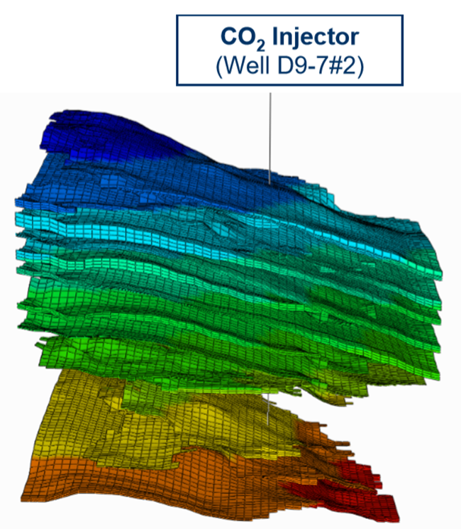
Figure 2: Reservoir modeling of CO2 injector well.
MVA
A major component of the Citronelle Project was to test and develop monitoring, verification, and accounting (MVA) techniques for the carbon dioxide (CO2) stored. A suite of technologies was applied and developed to demonstrate non-endangerment of underground sources of drinking water (USDWs) and to ensure CO2 did not migrate out of the injection zones. This involved several monitoring levels: surface monitoring, shallow groundwater monitoring, deep reservoir monitoring, and experimental MVA activities.
The surface monitoring program consisted of conducting soil CO2 flux surveys to detect any CO2 leakage. A tracer monitoring program was employed as a secondary surficial monitoring protocol. Tracer monitoring was conducted by injecting the CO2 stream with a mixture of perfluorocarbon tracers (PFTs). Since PFTs do not occur in nature, tracer buildups can be detected at low concentrations.
Groundwater monitoring was performed on a quarterly schedule to monitor for any evidence of CO2 impact on local USDWs. Multiple lines of evidence were required to determine that injected CO2 was not influencing the USDWs (Table 1).
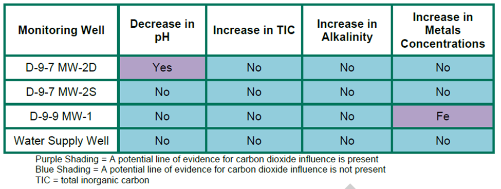
Table 1: Statistically determine potential lines of Evidence for CO2 influence.
Deep monitoring technologies were also deployed at the site to validate the CO2 containment in the target reservoir. Cased hole pulsed neutron capture (PNC) logs were deployed, which measure changes in formation gas saturation behind casing, as well as time-lapse crosswell seismic acquired between the injector and observation wells. Running crosswell survey in time-lapse allows for comparison of travel times between a pre-injection state and a state where saturation affects travel times.
A modular borehole monitoring (MBM) system was installed at the observation well as an experimental MVA tool. The MBM system was used to field-test a multi-sensor monitoring tool and to assess changes in inter-well formation saturation with time, sweep efficiency, and CO2-induced changes in the formation fluids’ geochemistry.
The combination of data collected from the multi-level suite of monitoring technologies demonstrated the effective containment of CO2 within the intended zones. This suggests that USDWs are not endangered by the CO2 plume, and that the Citronelle Dome forms an ideal storage complex for subsurface CO2 confinement.
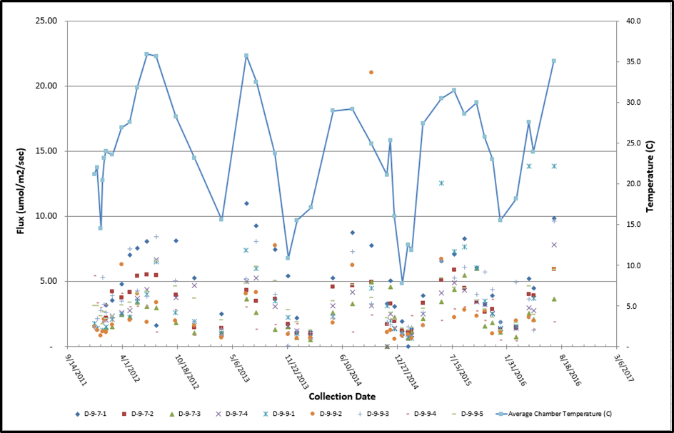
Soil CO2 flux monitoring results.
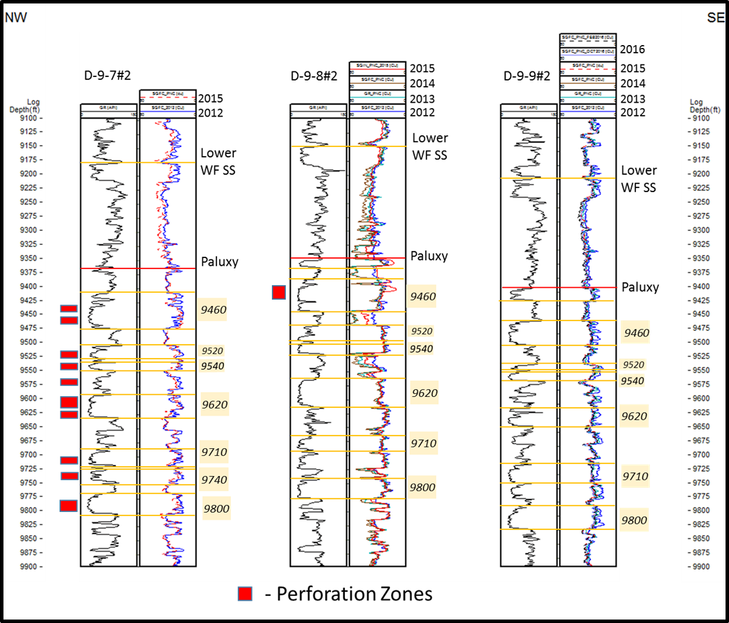
Time-Lapse PNC Logs of the D 9-7#2, D 9-8#2, and D 9-9#2. Baseline Curves are shown in Blue. Depths are in mD, feet.
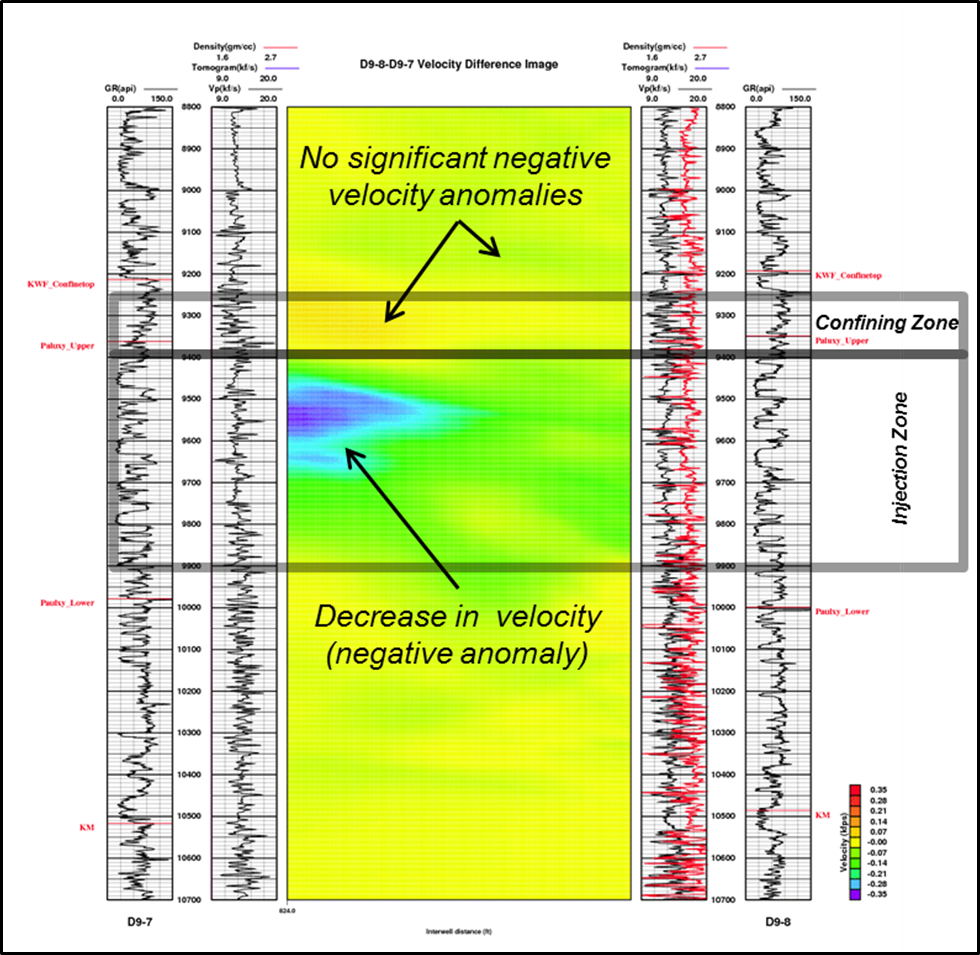
Pixelized difference tomography results without seismic reflection overlay showing positive velocity differences in warm colors and negative differences in cool colors. The D 9-7 #2 is to the left and the D 9-8 #2 is to the right.
Commercialization
Work completed during the Southeast Regional Carbon Sequestration Partnership (SECARB) project laid the groundwork for future fully integrated carbon dioxide (CO2) capture and storage (CCS) facilities in the southeast. In order to further the commercialization of carbon capture, utilization, and storage (CCUS) in the region, project partners share data, results, and lessons learned with the regional, national, and international community. The novel technologies and applications developed at the Citronelle and Cranfield Projects are used commercially and have been adopted at other CCUS sites as a standard of monitoring activities.
During project development, the SECARB partners focused on designing and operating a fully integrated project that would demonstrate the full CCUS value chain from a coal-powered electricity generating facility (the CO2 source) to a regionally significant geologic storage formation. The Citronelle Project was able to achieve and demonstrate the following objectives:
- Design and operate the largest commercial prototype pulverized coal integrated CCUS project in the United States.
- Investigate the CO2 flow, trapping, and storage mechanisms, both locally and regionally.
- Demonstrate the reservoir’s ability to maximize CO2 storage and minimize the areal extent of the CO2 plume.
- Investigate the adaptation of commercially available oilfield tools and techniques for monitoring, verification, and accounting (MVA) application.
- Investigate experimental CO2 monitoring tools that hold promise for future commercialization
- Document the complete permitting process.
- Assess and document a register of communication and project-related risks and a mitigation plan associated with the integrated project involving multiple entities and responsible parties.
- Analyze and assess the integration of project components.
The lessons learned from the Citronelle Project have been applied at several CCUS projects, including Mississippi Power’s Carbon Storage Assurance Facility Enterprise (CarbonSAFE; storage complex) project at Plant Ratcliffe and the Petra Nova Project in east Texas.
Proving the value and success in demonstrating a fully integrated CCUS project, SECARB’s 25-megawatt-electirc (MWe) demonstration at Alabama Power Company’s Plant Barry in Bucks, Alabama, served as the model for the Petra Nova 240-MWe capture system at NRG’s W.A. Parish Generating Station near Houston, Texas, completed in April 2017.
Within the SECARB region, there are significant geologic storage and CO2-enhanced hydrocarbon recovery opportunities that could be developed into commercial-scale CCUS projects. Opportunities for commercial-scale CCUS were initially focused on enhanced oil recovery (EOR), but the 2018 Balanced Budget Act made significant changes to previously available tax credits for CCS. The amendments to Section 45Q of the Internal Revenue Code (U.S. Code Title 26) tax credits increased the amount and duration of the tax credit available for geologic storage and storage resulting from utilization. The increased value of 45Q tax credits provides important incentives for the development of commercial-scale storage sites within the region. The ability to generate tax credits though utilization or geologic storage can be used to offset some, or all, of the costs of capture, making large-scale commercial application more viable in the region.
Within the SECARB region, several geographic areas have been identified that have good prospects for future commercial-scale CCUS projects:
- The Louisiana Chemical Corridor contains large concentrations of industrial emitters of CO2 and is located near oilfields that have been identified as good candidates for CO2-EOR.
- The Houston Ship channel contains large concentrations of industrial emitters of CO2 and is located near oilfields that have been identified as good candidates for CO2-EOR.
- Both the Louisiana Chemical Corridor and the Houston Ship channel have access to good onshore geologic storage options, as well as future offshore storage and utilization opportunities.
- Within Appalachia, enhanced shale gas recovery or enhanced coalbed methane may prove commercially viable through CO2 well stimulation.
- The Tuscaloosa Formation, which extends across large portions of the region, has similar properties to high-capacity storage formations in other regions and may be a good candidate for safe and secure geologic storage.
Commercialization efforts include education and outreach activities to foster additional support for commercial CCUS deployment within the region.