The Mitsubishi Heavy Industries (MHI) gasification technology was developed with the goal to maximize the gasifier efficiency (e.g., dry feed, and a unique two-stage reactor design) and reduce costs (e.g., air-blown to eliminate power consumption and capital cost of an oxygen plant). The development commenced in the early 1980s under a joint venture formed between MHI, the Japanese government, and several power/utility companies. This joint venture, called Clean Coal Power R&D Co., built a 2-ton-per-day (tpd) process development unit (PDU), and later, a 200-tpd pilot plant unit at Nakoso (about 200 km north of Tokyo) in Japan to test the technology. In 2004, a 1,700-tpd, 250-MW, integrated gasification combined cycle (IGCC) demonstration plant was built, also at Nakoso, which has since ended demonstration testing and now operates as a commercial IGCC power plant.
Operation
The MHI gasifier is a pressurized, upflow, entrained-flow slagging reactor with a unique two-stage operation, similar to the E-Gas™ gasifer. The MHI gasifier, however, is a dry-feed system, and the reactor internal is protected by a membrane wall, similar to those of the Shell and Siemens designs. The current focus of the effort is on air-blown (or enriched air blown) IGCC application. R&D activities are being carried out to develop an oxygen-blown system for coal to fuels and chemicals applications.
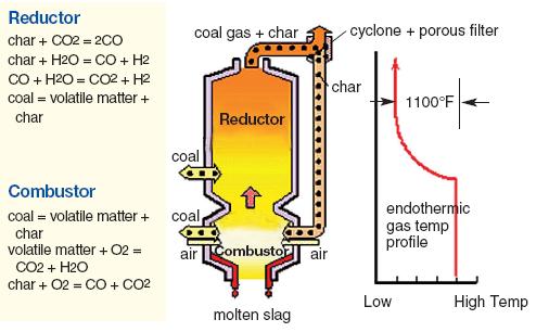
Figure 1 shows a simplified drawing of the MHI gasifier. The reactor consists of two sections (or stages): a lower combustor and an upper reductor. Dry milled coal is fed at two separate points into the gasifier with a portion being fed into the combustor together with air (or enriched air) where it is burned to produce carbon monoxide (CO) and carbon dioxide (CO2), plus water vapor. The temperature generated at the combustor is sufficiently high to melt the coal ash. The molten slag falls to the bottom of the gasifier where it a quenched in a water bath and then removed using a lock hopper system. The gas produced in the combustor rises to the reductor where the remaining coal is added, without any additional air. At the reductor stage, heat provided by the hot combustor gas is used to drive the endothermic gasification reactions. The reductor is operated at a lower temperature than the combustor. Any molten ash carried over by the upward gas is solidified. The syngas produced exits the reductor through a syngas cooler generating steam. A cyclone is used downstream of the syngas cooler to collect the chars and recycle them to the combustor section to increase the overall carbon conversion efficiency. The raw syngas leaving the reductor section of the gasifier is typically at at 2,200 °F, high enough in temperature that very little hydrocarbon gases and liquids are formed.
Figure 1: A Simplified Drawing of the MHI Gasifier
(source: Mitsubishi Heavy Industries, Ltd.)
Demonstration and Early Commercialization
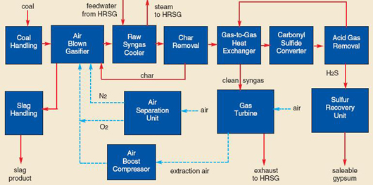
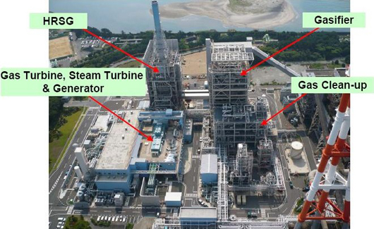
The MHI gasifier has been tested in both a 2-tpd PDU, and later, a 200-tpd pilot plant unit. Experience gained was used to design, build, and operate a 250-MW IGCC demonstration plant at Nakoso, Japan. Figure 2 and 3 show a simplified block flow diagram and a picture, respectively, of the demonstration plant. The plant operated in demonstration mode from September 2007 to March 2013. Nakoso IGCC has the following key features:
MHI’s dry-feed, two-stage gasifier.
Oxidant for gasification is extracted from the gas turbine with additional compression as required.
A relatively small air separation plant (ASU) is included to supply nitrogen as pressurized gas for coal transport, and the byproduct oxygen produced is added to the extracted air to enrich it. This ASU is typically 20-25 percent of the size that would require for an equivalent oxygen-blown IGCC plant.
Raw hot gas leaving the gasifier is cooled by the use of a high temperature syngas cooler integrated with a ‘membrane water wall’ which produces a saturated steam to be sent onto the heat recovery steam generation (HRSG) unit for superheating.
Cyclones and porous filters are used to remove the chars and recycle them to the gasifier.
The power block consists of a modified MHI M7010DA gas turbine with air extraction for the gasifier, a HRSG and steam turbine.
The plant gasifies approximately 1,700 tpd of coal, and produces 250 MW of power with an efficiency of 42 percent (low heat value net). Following completion of the demonstration in 2013, the Nakoso IGCC plant has been operated commercially by Joban Joint Power Company as a high efficiency power generating station.
MHI completed Front End Engineering Design (FEED) services for the Hydrogen Energy California (HECA) project in 2013. The HECA project is being developed by SCS Energy, LLC, a US power development company. The plant will use US coal and petcoke to generate hydrogen from syngas for electricity. A portion of the syngas will be used to produce fertilizer and the CO2 will be used for enhanced oil recovery. The HECA IGCC power plant will use MHI's oxygen blown gasification technology and have the capacity to generate up to 300 MWe (net) of power and up to 1.0 MT/yr Urea/UAN. Construction is planned to begin in 2015 with completion/start of operation slated for 2019.2
Figure 2: A Simplified BFD of Nakoso’s 250 MW IGCC Demo
(source: Mitsubishi Heavy Industries, Ltd.)Figure 3: View of the 250 MW IGCC Demo Plant at Nakoso, Japan
(source: Mitsubishi Heavy Industries, Ltd.)