Back to Top
Skip to main content
NETL Logo
Methane Mitigation Thermoelectric Generator (MMTEG)
Project Number
DE-FE0029060
Last Reviewed Dated
Goal

The project goal is to develop Natural Gas (NG) leak mitigation technologies that will enable companies to effectively mitigate leaks from midstream equipment and/or facilities (including pneumatic valves, controllers, and field gathering lines) and capture additional natural gas while removing their individual contribution to overall methane emissions. The project will develop and test an integrated thermoelectric generator (TEG)/burner system, as well as complete the design for a field pilot for oil and gas field operations. Targeted objectives for this project include:

  1. Design a prototype 24 We MMTEG with >7% efficient low NOx field system
  2. Fabricate an integrated TEG/burner per the 24 We MMTEG design
  3. Demonstrate the integrated TEG/burner in component testing
  4. Field system cost target of $1500 for 6 We system
  5. Equivalent greenhouse gas (GHG) reduction of >1000:1 (assuming long term factor)
  6. Target reliability of >99.99% for the TEG subsystem
  7. TEG module efficiency >9% peak (600ᵒC basis)
  8. Demonstrate a pilot field system in laboratory testing
Performer(s)

Gas Technology Institute, Des Plaines, IL 60018

Background

This project will use demonstrated advanced thermoelectrics to provide significantly higher system efficiency over commercially available TEG materials, coupled with an integrated burner-heat exchanger to achieve a low-cost system. The integration will utilize experience gained from another DOE program that developed a 1kW-class TEG for high-grade waste heat from automotive exhaust. The automotive TEG program is being completed by the Jet Propulsion Laboratory (JPL), who are the TEG developers for this program. This integration includes hot-side and cold-side heat exchangers, electrical circuitry, and control electronics.

Impact

The project provides a near-term energy opportunity to recover between 1–2 million metric tons of methane emitted by intermittent pneumatic controllers annually in the U.S., and potentially 6–12 million metric tons per year globally. This is a significant portion of greenhouse gas emissions. The proposed system offers a low-cost, direct retrofit solution that will provide a short payback to increase implementation of the system.

Accomplishments (most recent listed first)

The Program Kickoff Meeting was held October 25, 2016; the Program Management Plan was updated; and the Space Act Agreement with NASA/JPL was finalized and signed. The following technical items have been completed to date:

  • The Systems Requirement Review was completed with GTI and JPL
  • System balance has been updated for the overall system performance/requirements. JPL suggested employing a derivative of a previously developed TEG for this application
  • Analysis of the derivative TEG (from a DARPA program) showed it will meet or exceed the MMTEG program requirements, so the derivative TEG was selected
  • Adopting this previously developed TEG as a starting point reduces execution risk for this program and increases the prototype MMTEG wattage to 24 We
  • Continuing risk mitigation efforts
  • Heat transfer test to define heat transfer coefficient complete
    • Verified coefficient from the combustion products to the heat exchanger/hot shoe
    • Coefficient better than estimated by analysis
      • Updated value will be used in future analyses
      • Provides margin for adding compliant layers which also impact heat transfer
  • Burner tests are ongoing
    • Stable flame operation was achieved for a variety of mixing configurations
      • Prototype burner has been selected — Pre-mixed core with flameholding cup and swirled outer annulus with remaining air
    • Ignition system has been demonstrated
    • Currently testing a prototype combustor with a 3D printed heat exchanger/hot shoe
      • Initial vendor control system used to ignite and record data
      • Calorimeter heat sink simulating heat loss at future TEG locations
      • Pressure drop and combustion gas and TEG interface temperatures have been measured
  • TEG module thermal cycling test was completed
  • Module 6 was tested for 100 cycles at 20–30 °C/minute heat-up and cool-down
    • More severe than actual thermal cycle
    • 3.7% power loss from the cyclic testing
  • TEG module fabrication ongoing
  • Twelve initial modules completed
    • First four were process development
    • Two were used for thermal cycling
    • Two were damaged in fabrication
    • Four are complete
      • Module 7 is delivered 6.5 W when tested at temperature
      • Module 12 still requires aerogel encapsulation
  • Six modified modules will be completed as described below in System Development
  • Continuing Integrated TEG/burner design efforts
  • Sizing the combustor/heat exchanger/hot shoe/TEG/cold shoe/heat rejection to meet program requirements using the derivative TEG is complete
  • Modeling ongoing for the entire structure — all components
    • Thermal displacements defined
  • Selected concept for detail design
    • Hermetically sealing TEG modules by sealing in an enclosure
      • Defining structure/selecting materials to minimize heat transfer
    • Each TEG gets its own identical heat rejection fins
      • Allows for free movement in the axial and vertical direction and elements associated stress components
      • Opposing rejection plates are bolted down using spring bolts to apply 100–150 psi on the TEG modules
  • Initiated System Development tasks
  • Defined MMTEG system architecture to integrate TEGs into the system
    • Software logic charts complete
    • Control system piping and instrumentation diagram (P&ID) complete
  • Control system vendor identified issue of low efficiency to store energy in the battery due to high current resulting in large power losses
    • Changed TEG units for more dicrete TEG legs in series to increase the voltage and reduce the amperage and therefore losses
      • Requires new modules
  • Pressure drop trade study completed and low-power fan integrated into the system
  • Initiated control system design and fabrication
    • Initial version of system is complete and was used to ignite current burner tests and record test data
    • Final system will control the entire MMTEG system for testing
Current Status

Additional scope was added to the program. This includes fabricating the additional TEG modules and improving the system effieicncy by reducing the amperage from the modules into the battery.

MMTEG system design effort is continuing with the key challenge to design a compliant structure that allows for thermal expansion but does not structurally overload the TEG modules. The selected concept described above allows for thermal growth while maintaining the TEG modules under constant load. The detail design is currently in progress.

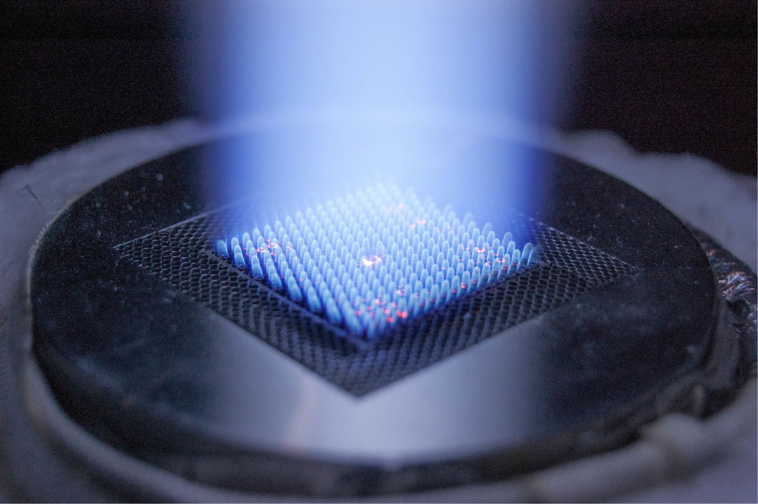
The new TEG modules will be completed as soon as the Space Act Agreement with JPL/Caltech/NASA has been signed for the additional TEG modules. Additional burner tests will be completed with the prototype combustor employing a 3D printed heat exchanger/hot shoe and calorimeter to simulate the TEG modules.

Subsequent tasks include an Integrated TEG/burner design review followed by assembly and test of the test article. Trade studies will be completed as part of the System Engineering task to define the overall system and its cost and optimize recoverable revenue by evaluating the following variables: TEG configuration, burner configuration and geometry, compressor reliability, controls minimization, safety, and burner pressure drop. The overall MMTEG system, including the control system and power management approach, will be defined.

Project Start
Project End
DOE Contribution

$1,815,288

Performer Contribution

$500,036

Contact Information

NETL – Gary Covatch (gary.covatch@netl.doe.gov or 304-285-4589)
Gas Technology Institute – Jeff Mays (jeff.mays@gastechnology.org or 818-405-9549)

Additional Information