Business

Business
The overall goal of the Phase I project was to understand the relationships between initial rock heterogeneity — such as natural fractures, grain inclusions, and anisotropy — and the dynamic propagation properties and static mechanical and hydrological properties of hydraulic fractures in shales. In Phase I, researchers used a combination of high resolution visualization experiments in the laboratory and coupled mechanical-hydrological simulations of the discrete fracturing processes.
The overall goal of the Phase II project is to understand the relationships between the properties of "problematic," ductile, and swelling-clay-rich shales and their impact on the time-dependent fluid/gas transport in the rock matrix and proppant-containing fractures. To accomplish this goal, core-scale laboratory experiments will be conducted under controlled temperature and stress, using several available natural shale samples with different ductility and clay compositions, and numerical modeling of the shale deformation and fluid transport will be performed and checked for accuracy against the laboratory results so that the models can be used for predicting the fluid transport in hydraulic fractures at the block-to-reservoir scales.
Lawrence Berkeley National Laboratory (LBNL)
Hydraulic fracturing is an indispensable tool for enhancing permeability of otherwise very impermeable shales containing oil and gas. For efficient and economical production of oil and gas from low-permeability rock, reservoir stimulation using hydraulic fracturing needs to take advantage of preexisting natural fractures to increase their drainage footprint. Both open and sealed fractures as well as other heterogeneities (such as inclusions and mineral grain boundaries) and anisotropy of the rock fabric play vital roles because these features interfere with the propagation of hydraulic fractures (causing kinking and branching) and resulting in a complex fracture network. However, how the geometry of the induced fractures — and the mechanical and hydraulic properties of the resulting fracture system — is affected by rock heterogeneity and anisotropy is not well understood, even though increasingly large numbers of hydraulic fractures are introduced in the subsurface without a clear understanding of how they propagate and evolve in reservoir rock. Furthermore, clay-rich, ductile shales are difficult to fracture, and the hydraulic fractures created in the rock tend to be short and have a smaller surface area. Proppant placed in these fractures tends to be embedded in the soft fracture walls, and the open space created by the fracture can be filled by mobilized clay minerals and by the expanded fracture walls if swelling clays (e.g., smectites, mixed-layer illites) are present in the rock.
To increase our understanding of hydraulic fracture propagation in complex, anisotropic, and heterogeneous shale, the Phase I laboratory experiments and numerical simulations investigated fracture propagation in in heterogeneous and anisotropic shale to visualize the properties controlling hydraulic fracture development and develop a predictive modeling capability will lead to (1) improved oil and gas recovery per well; (2) reduction in the total volume of injected fracturing fluid; and (3) avoidance of unexpected fracture propagation causing seal rock breach and fault activation. To address the challenges associated fracture sustainability, laboratory experiments and numerical simulations will be conducted in Phase II to investigate and understand (1) how hydraulic fractures produced in ductile shale behave over time to reduce its aperture and permeability; (2) how the proppant deposition characteristics (e.g., monolayer vs multilayer), grain size, and spatial distribution (isolated patches vs connected strings and networks) affect the sustainability of the fracture conductivity impacted by fracture aperture reduction resulting from rock deformation and clay mobilization; and (3) how the near-fracture shale-matrix fluid transport is affected by the evolving conductivity of the fracture.
The results of the Phase I effort increased our understanding of how hydraulic fractures propagate in complex, anisotropic, and heterogeneous shale to help optimize fracturing operations in the field and subsequent oil and gas production. The results from this work has the potential to lead to (1) a reduction in the number of oil and gas wells required to develop the field; (2) a reduction in the total volume of fracturing fluid injected; and (3) mitigation of unexpected fracture propagation, which may cause a seal rock breach and/or fault activation.
Results from the Phase II research effort will expand our understanding of the relationships between the properties of "problematic," ductile, and swelling-clay-rich shales and their impact on the time-dependent fluid/gas transport in the rock matrix and proppant-containing fractures. With this knowledge, and by choosing and controlling proppant types and emplacement strategy, hydraulic fractures with more sustainable permeability can be produced in currently underdeveloped shale hydrocarbon reservoirs.
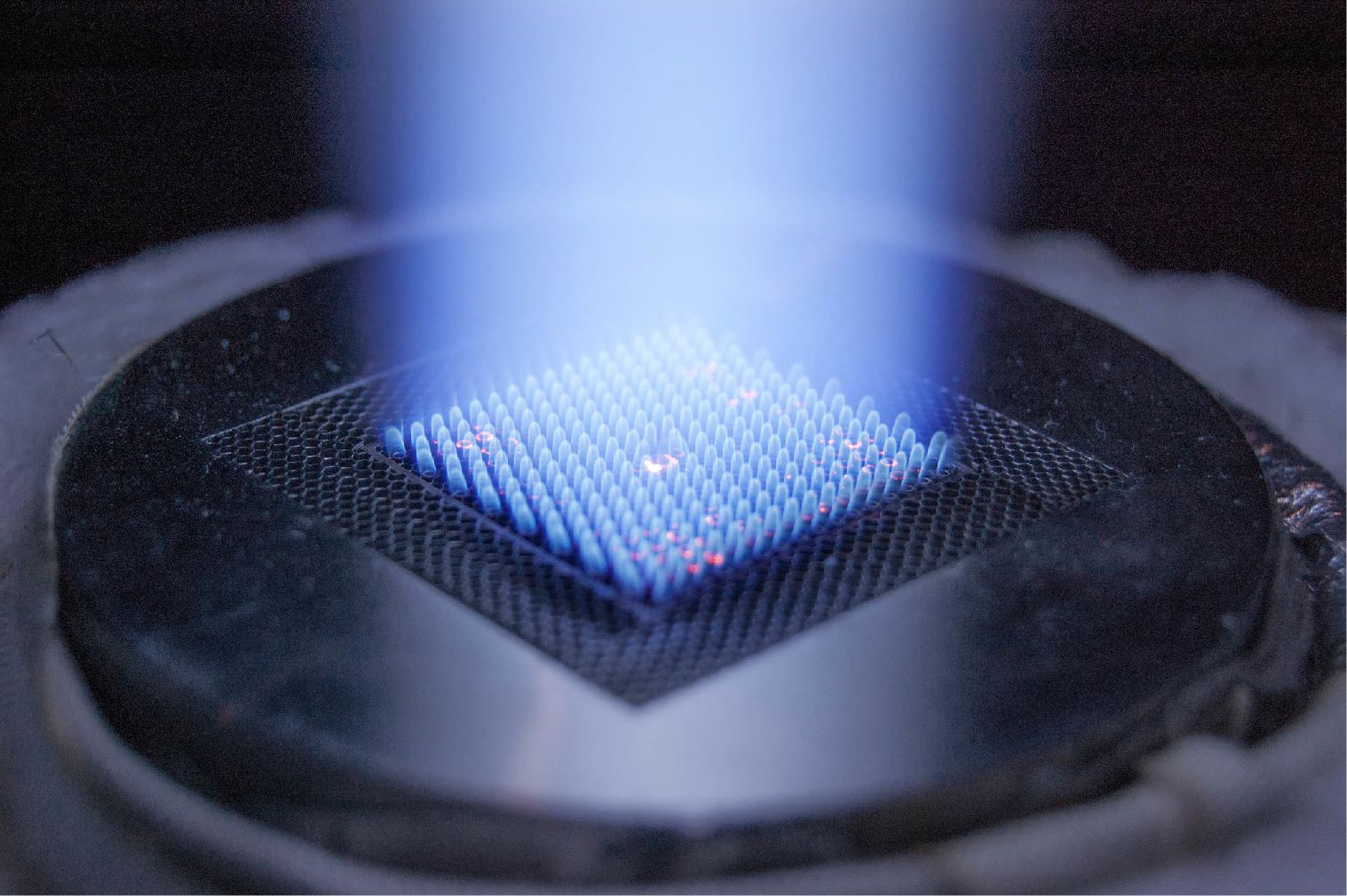
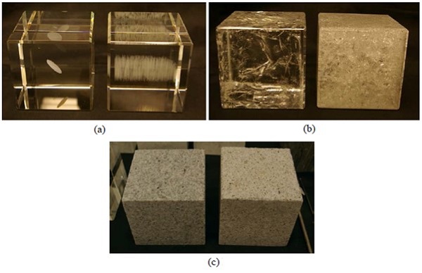
In Phase I, a polyaxial loading frame and a triaxial pressure vessel were modified and implemented for optical and X-ray computed tomography (CT) visualization of hydraulic fracture propagation in laboratory experiments using 4”x4”x4” analogue (glass) and shale blocks. The triaxial pressure vessel for X-ray CT was modified with redesigned and fabricated platens to accommodate the shale blocks used in the experiments. The triaxial cell was pressure tested and CT imaged with a mock sample prior to experimentation. Initial CT images indicated that low density fluids such as water could not be visualized with good resolution. A low-viscosity liquid-metal was prepared as an alternative fracturing fluid to enhance x-ray contrast. Two techniques were developed for producing fractured natural and analogue rock samples: (1) fractures in quartz-rich polycrystalline rocks and analogue samples (glass blocks) were thermally produced by leveraging the differential thermal expansion between mineral grains or the rapid thermal shrinkage of heated glass and (2) fractures in synthetic/analogue samples were created by laser engraving reproducible fracture geometries with variable fracture height and strength based on engraving height and density. Using the described methods, experimental samples were prepared with multiple fracture densities and geometries (Figure 1).
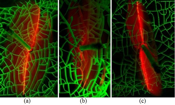
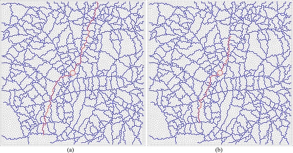
Phase I fracture visualization experiments have been completed to investigate the impact of stress conditions, fluid injection rates and viscosities, and preexisting fracture height and strength on hydraulic fracture development in analogue (glass) samples. Mancos shale blocks were also prepared for additional laboratory experiments, but the fracture visualization was ultimately unsuccessful due to the limited resolution of the medical CT scanner used in this project. To enhance optical visualization of the thin fractures, a fluorescent dye was introduced with the fracturing fluids. Fracture development was optically visualized through a series of high frame rate cameras in the vertical and horizontal directions. An acoustic emission monitoring system was able to map the location of small seismic events associated with fracture propagation. Stress conditions were found to play a major role in fracture development with fractures propagating perpendicular to the minimum principal stress direction. The effect of preexisting fracture height was found to influence hydraulic fracture propagation with more extensive fracture activation in samples with taller pre-existing fracture networks (Figure 2). Interpretation of the impact of preexisting fracture strength was challenging due to the formation of different fracture pathways in replicate experiments, but increased fracture interaction was observed with decreased fracture strength. The effect of fluid viscosity was also found to play a major role in fracture development. When injecting low viscosity fluid (water), the fracture development was much more rapid than observed with the high viscosity fluid (glycerol); furthermore, water injection resulted in hydraulic fractures that were minimally impacted by the preexisting fracture network (Figure 2). Finally, injection of high-viscosity fluid at elevated injection rates indicated that higher injection rates lead to more rapid fracture propagation and the formation of fractures that are less affected by the preexisting fracture network (Figure 2).
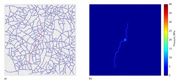
The Transport of Unsaturated Groundwater and Heat – Rigid Body Spring Network (TOUGH-RBSN) code was modified and tested for Phase I hydraulic fracture propagation simulations in complex fractured rock. The elastic and strength anisotropy algorithms were tested and verified for modeling laboratory scale samples under compression. The numerical code was initially tested for fluid-driven fracture propagation of a single fracture, and a sensitivity analysis was conducted to determine input parameters for the modeling experiments. A number of model grids were set up to represent the exact heterogeneity features of the 3D-laser engraved synthetic samples (Figure 3).
Using field data from the Mont Terri Hydraulic fracturing experiments, a field scale hydraulic fracturing model was developed as part of the Phase I effort. The results show some deviation of the fracture propagation from the bedding plane orientation; the fractures tend to be oriented more towards the maximum stress. However, the Mont Terri hydraulic fracturing experiments exhibited complex behavior that was not captured in the model.
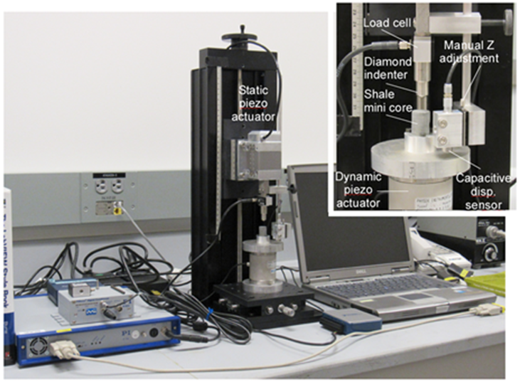
The Phase II research effort began on October 1, 2016. In Phase II, laboratory activity focused on shale property characterization and fracture compaction visualization experiments. Initial laboratory work focused on the development of an instrumented micro-indention system for examining shale elastic-plastic properties and grain-scale deformation using small chips and cores (Figure 5). A new LabView code was written for the micro-indention system to allow semi-automated loading and unloading tests for a given set of predetermined test parameters. Using the micro-indentation system and other laboratory equipment, shale property characterization and ductility measurements were completed on cores from the Barnett, Niobrara, Eagle Ford, Marcellus, and Mancos Shales. The shale properties that were measured include material density, anisotropic seismic velocity, dynamic elastic moduli, mineral composition, Young’s modulus, hardness, and ductility index. Based on the results of the shale property characterization, clay-rich Barnett Shale and Marcellus Shale samples from the Marcellus Shale Energy and Environmental Laboratory (MSEEL) appeared best for investigating the impact of fracture deformation and proppant embedment on fracture permeability loss while the Mancos, Eagle Ford, Marcellus (outcrop), and Niobrara Shales appear to be less sensitive to water and exhibit smaller ductility.
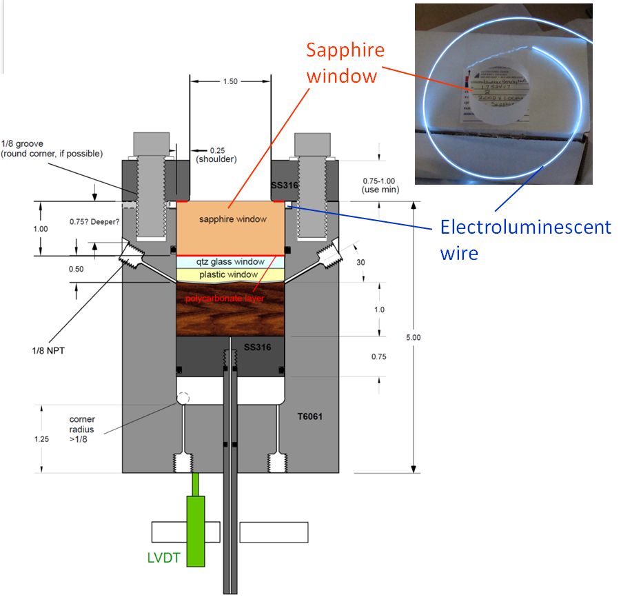
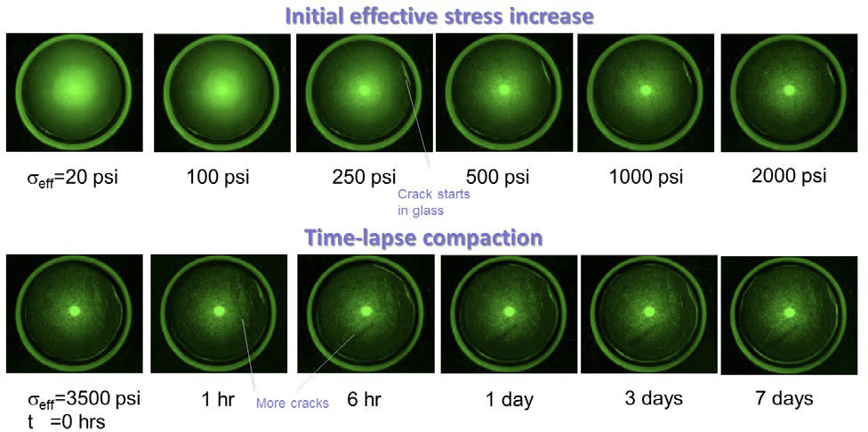
In Phase II, laboratory activity also focused on the design, fabrication, and testing of a shale fracture compaction visualization cell for use in fracture closure and proppant embedment experiments (Figure 6). After several design iterations of the X-ray transparent fracture compaction view cell, the system was successfully pressure tested and verified for optical and X-ray CT visibility of fractured rock samples. Initial laboratory tests were completed to assess fracture closure in shales of varying ductility prior to the introduction of proppant. In initial tests, all shale samples demonstrated large reductions in fracture aperture with time and increased confining pressure, as expected (Figure 7). In addition, very little shale deformation was observed. With the introduction of proppant, the fracture compaction behavior became more complex — both proppant crushing and proppant embedment during fracture closure were observed. Also, both the Barnett and Marcellus Shale exhibited more brittle behavior than was anticipated based on the shale property characterization.
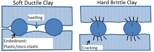
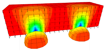
Phase II modeling work focused on the development and testing of models to evaluate proppant fate in brittle and ductile clays (Figure 8). Modeling approaches were developed based on LBNL’s coupled multiphase flow and geomechanical codes, TOUGH-FLAC and TOUGH-RBSN. These approaches were tested and used for simulating mechanistic grain to block-scale coupled hydraulics as well as mechanical interactions in the fracture and adjacent shale matrix. Specifically, for the current research, these approaches were tailored to capture coupled hydraulic and mechanical responses in proppant-filled fractures in shale based on previous laboratory and field studies reported in the literature and were refined based on new laboratory results developed in this project. The two codes were used to solve similar but complementary problems of proppant deformation/crushing in strong, brittle shale and rock matrix deformation/proppant embedment in ductile shale. TOUGH-RBSN simulations were completed to model discrete fracture propagation and crushing at the high stress concentration region around the proppant-rock contact in hard, brittle shale. Modeling results confirmed that the RBSN approach is capable of modeling fracture and damage behavior around the matrix-proppant contact, especially in brittle rock. The TOUGH-FLAC simulator was developed and tested to model proppant embedment and clay swelling in soft, ductile shale (Figure 9). Using the TOUGH-FLAC simulator, LBNL has successfully demonstrated (1) progressive proppant embedment with increasing contact between the shale and proppant involving contact detection in 3D, as well as large strain modeling with continuous updating of the geometric configuration; (2) proppant embedment using elastic and elasto-plastic constitutive models with permanent indentation pattern at the end of the simulation; (3) swelling expansion of the shale matrix when exposed to a change in pressure of changes in saturation, and the effect of swelling on fracture aperture; and (4) creep closure of fractures over several years with progressive embedment for proppants using visco-elastic model and creep parameters from laboratory data. Block-scale fracture compaction modeling is also underway with comparisons to recent experiments demonstrating promising results. These models were successfully used to model the laboratory experiments discussed above.
This projected ended on September 30, 2018. This research has been extended under a new research project (FWP-FP00008114), which will investigate fracture sustainability in more ductile shales and investigate possible mechanisms to avoid proppant embedment in order to retain fracture conductivity, ultimately enabling the development of these clay-rich, ductile shales.
$923,000
$0
NETL – Stephen Henry (stephen.henry@netl.doe.gov or 304-285-2083)
Lawrence Berkeley National Laboratory - Seiji Nakagawa, (SNakagawa@lbl.gov or 510-486-7894)
Final Technical Report (2019)
Laboratory and Numerical Investigation of Hydraulic Fracture Propagation and Permeability Evolution in Heterogeneous and Anisotropic Shale and Sustainability of Hydraulic Fracture Conductivity in Ductile and Expanding Shales (Aug 2017)
Presented by Seiji Nakagawa, Lawrence Berkeley National Laboratory, 2017 Carbon Storage and Oil and Natural Gas Technologies Review Meeting, Pittsburgh, PA
Phase 1 Final Report (July 2016)