Business

Business
The project goal is to design two sizes of an ultra-high-speed (10,000 rpm), inverted, configured electric motor specifically for drilling.
Impact Technologies LLC, Tulsa, OK
University of Texas, Arlington, TX
Drilling boreholes in materials at ultra-high speeds (>10,000 rpm) has been shown to penetrate faster than at lower speeds. Utilization of ultra-high pressures (in excess of 5,000 psi), abrasive and/or corrosive fluids, or other high-energy processes has also been shown to further increase penetration rate. A newly configured and patented motor design can utilize all the above-mentioned advanced drilling techniques for drilling difficult materials on the surface and in the earth. The chief benefit of this “inverted” motor configuration over conventional motors is that the internal high-pressure fluids are not in contact with the internal motor power components, wires, or cables. An electric version of this new configured motor is being deployed in this project to drive cutters at these ultra-high speeds. With this motor it will be possible to drill extremely hard and/or deep geological rocks and materials that currently cannot be drilled efficiently, economically, or even at all.
Results
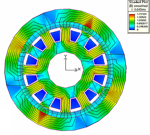
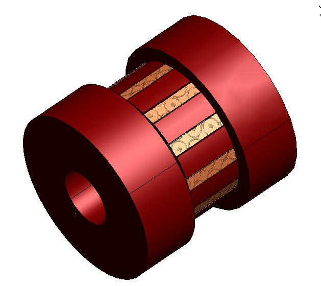
Researchers have developed PMSM (permanent magnet synchronous machine) electromagnetic designs of both radial and axial motors for rotational speeds up to 10,000 rpm in two outer diameters (OD). Finite element analyses (FEA) of the magnetic saturation and power/torque output have been made at various speed and loading conditions. Mechanical 3-D models have been prepared based on those designs. Bearing and seal materials have been studied, and manufacturers have been contacted to provide them. The project milestones completed to date are the:
Benefits
Ultra-high-speed drilling, as enabled and powered by this patented configured motor, has the potential to provide a step change over current drilling and boring processes. Its application to drill deep, hard rocks and/or microholes will allow drilling of targets that are not currently possible or that are uneconomic to attempt. This will result in lower costs to drill and find new reserves. Utlra-high-speed drilling has applications in the oil and gas industry (exploration, drilling, completion, and production), gas storage industry (enhanced deliverability), geothermal industry (injectivity), road boring, resource mining, utility trenchless installations (telephone, fiber optics, communications, water, sewer, etc.), pipeline installations across roads and rivers, and job/fabrication shops.
Summary
This project began in October 2004 and initially focused on the applications and bits that can be used for these ultra-high-speed drilling applications. It was important to estimate the required load, torque, horsepower, and sizes of the motors. From this study, it was found that few cutter elements and bits can withstand the generated heat, abrasiveness, and shock of this environment, although current work in this area is encouraging. A separate DOE project with TerraTek is studying cutting elements at these ultra-high speeds.
Based on this initial work, the motor requirements were set as a first pass for the electromagnetic design. The two motor sizes selected had ODS of 1.69 inches (to pass through standard 2⅜-inch tubing) and 3 inches (to pass through standard 4½-inch casing), with the variable lengths and motor power sections stackable to meet any required power requirement. The internal and external fluid flows can efficiently cool the electrical/magnetic- and bearing/seal friction-induced heat load. Thus a minimum flow rate will be required. Air gap clearance is an ongoing concern, and proper spacing (via design and bearings) is required. Based on the simulations made, axial motor designs were found to be superior to radial designs based on unit power generated. Both power control and power inverter boards have been designed. The motor can be variably speed controlled. Power and torque output of the motor is very favorable over its full speed range.
Materials, methods, and manufacturers of bearings and seals have been identified and contacted. Final selection of these has not been made. Researchers have recently dropped the internal gas requirement in favor of a non-conducting internal fluid. Internal designs will be modified to minimize turbulence effects. This change has allowed a seal to be designed, where otherwise (with internal gas) it could not be designed for no seepage and for ultra-high speeds.
(July 2007)
Impact Technologies completes project that designed ultra-high-speed (10,000 rpm) electric inverted configured motors for drilling. Three (3) designs have been made for two sizes, 6.91 cm (2.72 inch) and 4.29 cm (1.69 inch) outer diameters, of a patented inverted configured permanent magnet synchronous machines (PMSM) electric motor specifically for drilling at ultra-high rotational speeds (10,000 rpm) and that can utilize advanced drilling methods. Benefits of these motors are stackable power sections, full control (speed and direction) of downhole motors, flow hydraulics independent of motor operation, application of advanced drilling methods (water jetting, abrasive slurry jetting and more) and the availability of signal/power electric wires through motor(s) for instruments at the bit and additional motors. Key features of the final designed motors are: fixed non-rotating shaft with stator coils attached; rotating housing with permanent magnet rotor attached; bit attached to rotating housing; internal channel(s) in non-rotating shaft; electric components that are hydrostatically isolated from high internal pressure circulating fluids ("muds") by static metal to metal seals; high power density axial configured, permanent magnet pulsed modulated drive; liquid filled motor with smoothed features for minimizing turbulence in motor during operation; stator and rotor axial spacing fixed through thrust/journal bearing; inner components spring loaded with a sliding seal; new inverted coated metal-metal hydrodynamic bearings and combined seals. Based on this design work, 7.64 cm (3 inch) OD, low speed versions of the PMSM electric motor in an inverted radial configuration are being built under a 2006 Oklahoma Center for the Advancement of Science and Technology (OCAST) "proof of concept" grant. The final report is available below under "Additional Information".
Funding
This project was selected in response to DOE’s Oil Exploration and Production solicitation DE-PS26-04NT15450-1, Microhole II.
$165,882
$55,441 (25 percent of total)
NETL - Virginia Weyland (virginia.weyland@netl.doe.gov or 281-494-2517)
Impact Technologies - Ken Oglesby (oakk@aol.comr 918-627-8035)
Final Project Report [PDF-12.2MB]