Business

Business
The production of coalbed natural gas (CBNG) yields saline produced water as a by-product. This produced water must be disposed of according to environmental regulations, which increases the overall cost of CBNG production. Technology exists to treat CBNG produced water. However, there are some limitations to these methods. The treatment of produced water via hydrate formation may eliminate some of these limitations. This project aims to use gas hydrate treatment to complement existing treatment methods and to reduce treatment costs.
Oak Ridge National Laboratory (ORNL), Oak Ridge, TN
Gas hydrates, which occur naturally, often constitute an undesired product during gas production and gas transport operations. They are also being considered for various industrial applications, including water desalinization, gas separations, and energy storage and transportation. In general, gas hydrates form at low temperatures and high pressures. Gas hydrates consist of hydrogen-bonded networks of water molecules and gas molecules. The hypothesis is that, if water is incorporated into gas hydrate, the dissolved solids will be excluded from the hydrate. Previous studies have attempted to treat water using hydrate and have recognized the potential of this method. The novel feature in this project is the development of the technology to produce hydrate on a continuous basis, which would facilitate its scale-up to industrial operations.
The formation of gas hydrate constitutes a product-limited reaction because of mass-transfer and heat-transfer limitations. At favorable thermodynamic conditions, hydrate formation occurs instantaneously at the hydrocarbon/H2O interface at given temperatures and pressures, and an impermeable layer of gas hydrate is formed over the entire surface area of the interface. Therefore, the potential for hydrate formation is limited by a surface barrier to mass transfer that prevents the interaction between the two reactants, thus diminishing reaction rates and limiting conversion. A means of reducing mass transfer resistance is to increase interfacial area. Maximizing the surface area of interaction between reactants during hydrate formation is achieved by dispersing one of the hydrate-forming species into a continuous flow of the other hydrate-forming species. A pilot-scale CJHR was designed and developed at ORNL to overcome the product-limited aspects of hydrate formation. This is achieved in the CJHR by spraying the dispersed phase into the continuous phase to generate the smallest possible droplet size. The interfacial area maximized in this way not only decreases mass transfer barriers but also increases heat dissipation along the reaction interface.
In this work, the application of the CJHR and possible modifications to the original design are investigated to develop technology suitable for CBNG produced-water treatment.
Results
Theoretical calculations and experimental studies have been performed in parallel, and theoretical predictions were used to guide the design of experiments. In that regard, hydrate thermodynamic equilibrium and stability calculations have been employed for the selection of experimental parameters, such as the guest gas mixture to be used in hydrate production and ranges of operating pressure and temperature.
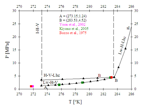
Early in this work, carbon dioxide (CO2) was used for proof-of-principle—i.e., a preliminary test of the hypothesis that hydrate formation would purify water by excluding solids from the hydrate structure—and for a preliminary design of a water purification process. Equilibrium thermodynamic calculations predict that CO2 forms the sI type of hydrate within the range of temperature used in this study. Up to a temperature of 283.5 °K (10.4 °C), increments in temperature are met by moderate increments in equilibrium pressure (i.e., pressure required for incipient hydrate formation), while the pressure required for the formation of gas hydrate increases exponentially at greater temperatures (see Figure 1). Any process aiming to utilize CO2-hydrate formation for water purification purposes would be limited to temperatures lower than 10.4 °C due to the potentially higher cost and operating difficulties associated with high-pressure processes (pressures above 5 MPa). Therefore, the temperature of initial tests in a water purification process utilizing CO2 as hydrate former was maintained below 8 °C.
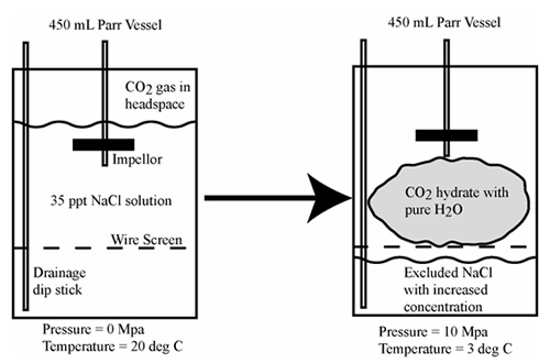
Proof of principle experiments were conducted in a small-scale pressure vessel. These experiments used a water solution with a starting salinity of 3.5 percent and were conducted by forming hydrate in a 450 mL stirred tank reactor filled with ~400 mL of salt water (see Figure 2). Hydrate was separated from the excluded saline water and then dissociated. The salinity of the thawed water was measured. In some experiments, a nucleating agent (Snowmax®) was introduced. The preliminary experiments showed that the salinity of water after dissociation of the hydrate could be significantly reduced due to incorporation of pure water into the hydrate structure. For example, the initial salinity of the tested water (35 ppt) was lowered to about 9 ppt without the utilization of nucleating agents. Experiments using nucleating agents to facilitate hydrate formation yielded salinities of 5 ppt and 2 ppt.
Continuous hydrate formation for water treatment was investigated via the utilization of a continuous-jet hydrate reactor (CJHR). The CJHR (see Figure 3), developed at ORNL, was mounted inside the Seafloor Process Simulator (SPS), a cylindrical Hastelloy C-22 vessel of 31.75-cm diameter, 91.44-cm length, and 72-l volume. The SPS allows operational pressures up to 17.2 MPa to be maintained during laboratory experiments. The entire reactor was submerged and at thermodynamic equilibrium with the vessel. This setup required the use of a submersible pump (Seabird SBE 5T) to circulate water from within the SPS, at a controlled flow rate, into the CJHR. Within the CJHR, the water was then mixed with liquid CO2 injected from outside the SPS. This CO2 was injected via a pulsating pump from a pressurized cylinder. During the operation, water was recycled. The SPS was configured with a pressure transducer, and a thermocouple was submerged below the waterline within the SPS. LabView software was used to monitor and record internal pressure and temperature conditions. The SPS was filled with spiked water, and nitrogen was used to pressurize the vessel. Pressures were maintained within a range of 0.3 MPa to 10.3 MPa for all experiments. Initial salinities of spike water were kept between 6,000 TDS and 7,000 TDS, and initial temperatures ranged between 1.5 °C and 2.0 °C. Continuous hydrate production was performed inside the pressurized vessel for up to 20 minutes, leading to the formation of several liters of hydrate. After hydrate production stopped, unreacted water was drained from the vessel. The hydrate was allowed to dissociate, and the salinity of the water released during hydrate dissociation was monitored.
Two different approaches to collect the produced hydrate inside the SPS were investigated: Hydrate could be stored under unreacted water or above the unreacted water level. In experiments with hydrate stored under water, the CJHR was oriented so hydrate was extruded downward onto a submerged screen, while on experiments with hydrate stored above the water level; the reactor was oriented upwards with the screen placed at the reactor outlet. The objective of choosing two different hydrate-collection methods was to investigate their effect on the amount of unreacted water trapped in the product and to prevent premature hydrate dissociation. It was expected that storing hydrate above the water level would reduce premature dissolution of hydrate by avoiding contact with water, and that it would allow saline water to “drip” off of the hydrate after formation.
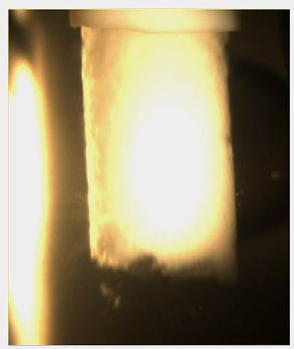
In all cases, hydrate-composite particles composed of CO2 hydrate, unreacted liquid CO2, and unreacted water were formed (see Figure 4). Experiments conducted with hydrate stored above water after formation yielded more positive results in the amount of hydrate that could be effectively separated from unreacted water. After formation of hydrate for 20 minutes with the in-water setup, only slightly more than 8 L of hydrate was formed. The above-water setup produced similar amounts of hydrate in 10 minutes or less. This was attributed to the premature dissolution/dissociation of hydrate taking place at a higher rate when in contact with water. The salinity profiles of hydrate dissociated after unreacted water had been removed were ultimately very similar. The initial salinity of dissociated hydrate composite is similar to the salinity of produced water. As hydrate dissociates, the salinity of treated water decreases. The profiles tend to increase slightly just after dissociation begins. This may indicate the entrapment of ions within the hydrate composite. As the hydrate dissociates, these ions are the first to be released, and there is a small increase in salinity. Salinity decreases thereafter to as low as 1,000 TDS.
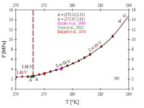
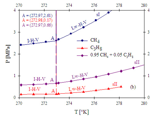
Since one of the comparative advantages of a water-treatment process using gas hydrates stems from the fact that it would be at the wellhead, the use of methane (CH4) as a gas precursor for gas hydrate formation is highly desirable. Figure 5 presents calculation results for a) the pressure-temperature equilibrium diagram for methane hydrate formation, and b) a comparative diagram presenting equilibrium curves for pure methane, pure propane, and a methane-rich mixture containing methane and propane. CH4 hydrate forms at comparable conditions of pressure and temperature as CO2 hydrate. Additionally, the presence of dissolved solids such as salt displaces the equilibrium towards higher pressures and temperatures. The higher the concentration of dissolved solids, the larger the shift of the equilibrium curves. Therefore, a hydrate-based water treatment process utilizing CH4 hydrate will be limited in terms of temperature of operation (e.g., temperatures lower than 7 °C to work with pressures lower than 5 MPa). When a mixture of two gases forms gas hydrate, as in the case depicted in Figure 5, it is expected that the conditions of thermodynamic equilibrium and stability for the mixture lies in between the two boundaries of the equilibrium curves of the pure components. Propane hydrates are stable at lower pressures than CH4 hydrates, at the same temperatures and, in contrast with CH4 hydrates, C3H8 hydrates present sII structure with higher associated hydration numbers (i.e., more water molecules participate in the hydrate structure). Hydrate formation from a mixture of CH4 and C3H8 with a small amount of C3H8 (5% on a molar basis) occurs at significantly lower pressures than the ones required for pure CH4, at the same temperature range. Therefore, the use of small amounts of propane to reduce pressure requirements will be explored during the produced-water treatment process design in this work.
Phase one of the research is nearly complete. Based upon laboratory research conducted by ORNL a preliminary design of a field ready prototype has been completed. Initial research by ORNL using carbon dioxide and simulated saline produced water defined the concept and verified the concept feasible for significantly reducing salt concentrations in the water. Initial laboratory tests conducted showed the hydrate process capable of reducing the salt level in the synthetic produced water from 35,000 to 2,000 ppm.
Additional, laboratory-scale experiments have been conducted by ORNL using the synthetic brines and varied gas compositions. Methane hydrate formation was investigated in a series of laboratory-scale experiments, propane hydrate formation in another series and a final series in which a gas mixture of 95% methane and 5% propane was used to form the hydrate. Successful hydrate formation was achieved using each of the three gas mixtures. Safety, economic and technical factors are currently being considered to determine the final hydrate to be produced.
ORNL is currently using the data generated thus far to optimize the performance of their continuous-jet hydrate reactor (CJHR). Once this is completed they will undertake lab testing of hydrate formation using actual field brine. In closing, ORNL also communicated results of laboratory-scale experiments and provided BC Technologies, Ltd. (BCT) with a CJHR for initiation of prototype development. For additional information regarding the ORNL research please contact Costas Tsouris (tsourisc@ornl.gov or 865-241-3246).
Benefits
The results of experiments with CO2 indicated that the salinity of spiked water, simulating CBNG produced water, can be reduced using hydrate treatment. Additionally, hydrate can be formed continuously with the CJHR, which can facilitate a possible scale-up of the process. However, there are still several problems that need to be solved. Besides the fact that CO2 is not an existing resource at coalbed mines, the hydrate obtained with CO2 in the CJHR constitutes a composite product. Salinity is excluded from the hydrate structure, but residual salinity is trapped inside the composite particles along with untreated water and liquid CO2. Therefore, further experimental work and reactor design improvements need to target CH4 and/or CH4-C3H8 mixtures and to have operating conditions that allow for the production of a less-cohesive hydrate product to minimize accumulation of residual salinity.
Another important design addition is a heat transfer element to facilitate hydrate dissociation and release of treated water and gas, thereby reducing process time.
Summary
Gas hydrates are naturally formed at low temperatures and relatively high pressures. They are crystalline materials based on hydrogen bonding and form different structures, depending on the type of gas molecules. These materials are investigated in this work as a means for desalination of CBNG produced water. Initial experiments conducted with CO2 demonstrated the potential of this approach. The hypothesis that solids are excluded from the hydrate structure, effectively separating clean water, was confirmed during preliminary experiments. A CJHR developed at ORNL to produce hydrate on a continuous basis was tested for its applicability to water treatment. The CJHR receives produced water and hydrate-forming gas at one end and extrudes hydrate solid particles at the other end. Experiments using the CJHR were conducted using CO2 as a guest gas inside a 72-L pressure vessel that allows visual observation of the hydrate particles. CO2 hydrate composite particles were successfully produced in a continuous operation from liquid CO2 and synthetic CBNG produced water. Dissociation of the hydrate particles regenerated the gas for recycling and produced low-salinity water. Mixtures of gases, including methane and propane, are planned for future studies with the goal to reduce the pressure required for hydrate stability and facilitate the application of the technology at the wellhead. These studies are guided by thermodynamic hydrate-stability simulations of gas mixtures.
(February 2008)
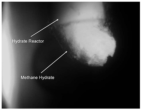
Experimental work on the application of the CJHR for the continuous formation of CH4 hydrate started at the beginning of this year. The new experimental design was based on CO2 hydrate formation experiments and information of CH4-hydrate thermodynamic equilibrium calculations. Methane hydrate experiments differ in that they convert methane gas into hydrate, while CO2 hydrate experiments convert a liquid phase into hydrate. Because of the change in the phase of one of the reactants, the experimental set-up had to be modified. A booster gas pump is now used to introduce the gas reactant into the SPS and the CJHR. The initial experiments successfully formed methane hydrate continuously without the necessity for modifications to the original design of the CJHR (see Figure 6). However, modifications to the original design of the CJHR are being investigated to allow for a better separation of the formed hydrate and minimize residual salinity trapped along with unreacted water within the hydrate particles.
CBM produced water experiments were focused on isolating the operating conditions for continuous formation of methane hydrate. Optimizing these conditions will be the key in developing a CBM produced water treatment process. Numerous experiments have been conducted to constrain these conditions. A continuous-jet hydrate reactor, designed for continuous hydrate formation, was employed for these experiments. Experiments were conducted in the ORNL Seafloor Processes Simulator (SPS). The continuous-jet hydrate reactor maximizes surfaces area between water and methane, thus increasing hydrate conversion.
Hydrate was formed in simulated produced water of varying salinity at between 1.0º and 2.0ºC. The flow rate of methane introduced into the SPS was held constant. Hydrate was formed for 150 s while pressure and temperature changes were monitored and recorded using LabView® software. Conversion ratios of hydrate were based upon pressure changes within the SPS versus methane introduced to the SPS and dissociation rates of methane in water. Various values of flow rates, hydrate nucleators, and salinities were tested.
Experiments showed that increased water flow rates yield increased hydrate formation. This is a result of several factors including increased mixing, and increased heat dispersion. The introduction of a hydrate nucleator (Snowmax®) also resulted in increased hydrate conversion. Salinity variations, gas mixtures, and other characteristics are being explored to increase hydrate conversion. Determining these conditions will increase the efficiency of CBM produced water hydrate treatment.
In parallel to the experimental work on hydrate formation, we have developed a model that incorporates thermodynamic equilibria, dissociation kinetics, and heat transfer to yield the dissociation rate of methane hydrate and the temperature history in the SPS during dissociation. Modeling results show that hydrate dissociation is a slow process even in the case of fast depressurization. This model will help us in the design of a process for CBM produced water treatment via hydrate formation and dissociation.
A No-Cost Extension has been requested and is currently being processed. The extension will modify the end date to December 31, 2008.
Funding
This project was awarded under DOE solicitation DE-PS26-05NT42395.
$175,000
$0
NETL – Jesse Garcia (jesse.garcia@netl.doe.govor 918-699-2036)
ORNL – Costas Tsouris (tsourisc@ornl.gov or 865-241-3246)
Publications
Two oral presentations resulting from this work were delivered at international conferences:
C. Tsouris, P. Szymcek, S. McCallum, P. Taboada-Serrano, M. Elwood-Madden, T. Phelps, J. Boysen, and D. Boysen, “Coalbed-Methane Produced-Water Treatment Using Gas Clathrate Hydrates,” 13th International Petroleum Environmental Conference, San Antonio, TX.
P. Taboada-Serrano, P. Szymcek, S.D. McCallum, C. Tsouris, “Formation of Mixed Gas Hydrates: A Thermodynamic Study,” AIChE Annual Meeting, San Francisco, CA.